A PORTABLE glass melting furnace
by Anna Viktoria Norberg
From a Post Graduate research project
Edinburgh College of Art
1997
This furnace was designed for the purpose of bringing melted glass
outside the glass making workshop. It comes apart into manageable pieces, even for a not very strong person like me. It runs on propane gas exclusively and needs no electricity. From first firing it is possible to have melted (but seedy) glass in about 3 hours.
I have used it in various locations primarily for my performance piece 17 minutes.
The Design
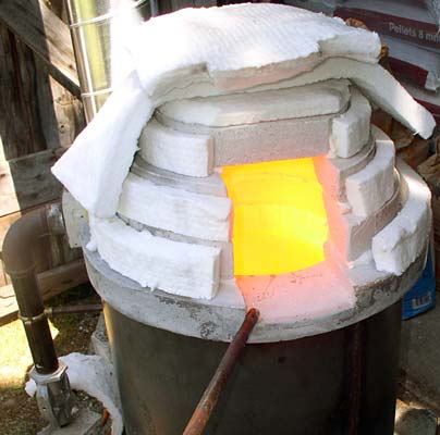
The furnace I designed is based on a common glory hole design, a metal drum lined with ceramic fibre. However, I flipped the design vertically and added a lid. Because the main purpose of the furnace was portability the lid is made of 4 rings stacked on top of each other. Much thought was put into finding good gathering angles. See design sketches below.
The burner is placed at the top and the flue hole at the bottom, just underneath the crucible, at a tangent with a 360° rotation. This directs the hot gases to circle around the outside of the crucible before they exit.
Between the cast refractory rings I put thin layers of ceramic fibre. I also used ceramic fibre blankets to make a simple "door" as well as insulation over the top. It is my intension to create a metal hood over the top to improve on the insulation.
The drum is 48 cm in diameter with 10 cm insulation and a 22.5 cm crucible. This leaves about 2.5 cm gap between the crucible and the wall. The total height is about 65 cm. I have raised it on bricks for a good gathering angle that fits me.

See more images at the bottom of the page.
The materials and construction
Metal Drum
The drum is made from 3 mm mild steel rolled and welded together. In the original design it was made in two sections; a bottom part which held the refractory base and an upper part to hold the ceramic fibre. In my remake from 2007 it is just one piece.
The castable
In Scotland I used a castable from MacGregor and Moir called MacKast 1600. In my 2007 remake of the furnace I used a much finer castable mix called Plicast 3000. For the molds I used thin metal which could be bent into rings in the different sizes. I cut out pieces of polystyrene to create the holes and to prevent water from escaping I used plastic film in the joints. For the inside of the top I used 8 pieces of 2.5mm stacked MDF board, which I then turned on a lathe to make a negative shape of the core. The MDF is screwed together and I used 2 sheets for each ring. It is very important to get the right mixture of castable and not use too much water. The bottom piece was made a little smaller to be fitted in after it was dry.The castable mixture needs to be properly dried, preferably in a kiln following the manufacturers instructions.
Ceramic fibre
Under the refractory base I placed a 5 cm thick layer of ceramic fibre. To prevent the fibre from getting compressed, and thus loose its insulating properties, I made small feet which the base is actually standing on. The ceramic fibre for the walls was cut into strips. I calculated the circumference and then added about 20% (or as much as was possible) to make it compact. The strips were lined up on a strong plastic sheet and then compressed and rolled into a circle. With the help of strings, and a little practice, it was possible to compress the ring small enough to force it into place. The inner circumference is compressed thus keeping the ceramic fibre in place whilst the outer, less compressed circumference will maintain its insulating properties.
The Chimney
The hole for the flue was cut into the fibre directly below the burner at a 90° angle. The chimney is made from an standard 15 cm ventilation pipe with a 90° bend and lined with ceramic fibre to protect the metal. It is supported by a stand and simply placed next to the furnace. Because I am unable to calculate the exact size of the flue I cut a horizontal slice in the chimney and use a thin kiln shelf as a damper.
The Crucible
The crucible is a Dyson sillimanite 22 cm in diameter and cut down to the height of my design 22 cm. Due to the nature of the rapid temperature changes a sillimanite crucible is absolutely necessary. It is important to follow the manufacturers instruction how to fire sillimanite in order for the crucible to last. It is sitting on a small base off I cast myself about 3 cm off the bottom. I usually sprinkle some sand in the bottom to prevent the crucible from sticking to the glass that escapes when I charge.
The burner
I am using a small injector burner built by furnace designer and maker Peter Wren Howard, Stourbridge, UK. According to my notes he used a 1 1/4 injector and an Amal jet no 95. It is also called a venturi burner and it pulls in the air into a mixer pipe and thus need no external fan - perfect for the portable furnace! It has a cast burner block, which Pete warned me would crack if it was to be inserted into the ceramic fibre. In my design it fits in between two of the rings.
In conclusion
A big plus with creating a furnace from smaller parts is that they are easy to replace when they crack or wear down. In my original design I also had a hole in the bottom for the glass to escape when the crucible where to crack (someone told me it is most likely to crack when full). However, with the burner on the top the escaping glass would probably soon cool too much to flow and remain in the furnace. I have concluded that when that happens I will need to replace all the bottom parts anyway.
Firing
The first time a fire the furnace after transportation I usually bring it up slowly. The critical stage is passed when the refractory is red hot at about 700°C. After that I bring the pressure up to about 1 bar and keep the damper where the temperature climbs the fastest. I have noticed when I am outside the weather probably affects the best damper setting. I have a furnace diary where I note the temperature as well as how much gas, air, and damper size I use for each furnace run. When the crucible is red hot at about 1000°C I charge the pot with crushed glass. With about 20-30 min in between I charge 3 times to fill the pot. After that I let it run high for about 1 hour until I reach 1170°C, then I turn it down to keep it at about 1180-90°C. The glass is very seedy but that does not matter to me. I have never tested to see how much time it takes for the glass to clear. After I am done I make sure the crucible is as empty as possible and then I turn the gas off. I also take off the chimney and plug up the hole, and leave the furnace to cool off for about 12 hours. If I need to move it right away just I take off all insulation and after another 6 hours all parts are warm to touch.
The propane gas usage have been on average a little less than 1 kg an hour and I use the 19 kg bottles because they are easy to carry and buckle to a car seat. A 19 kg bottle have lasted about 19-22 hours.